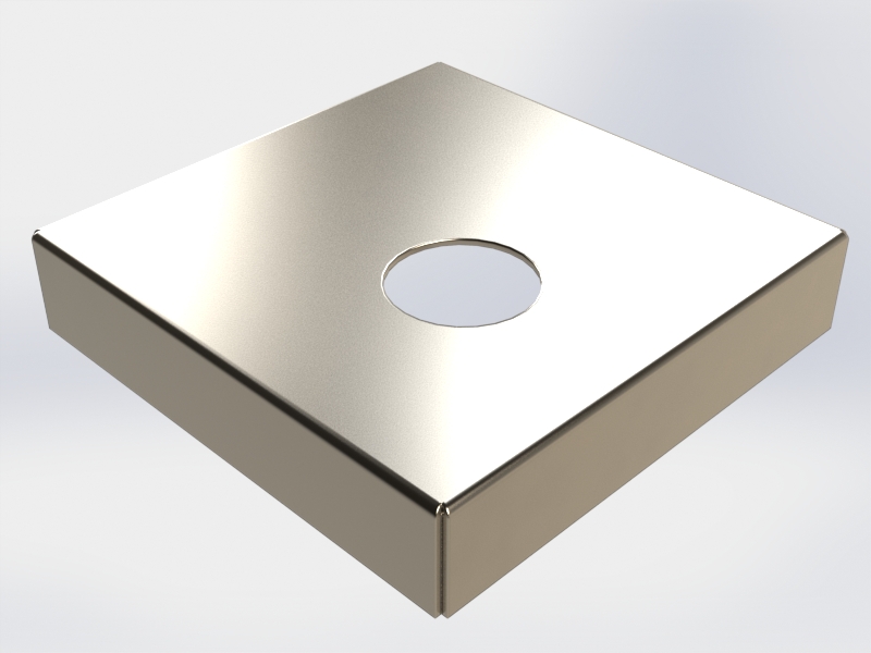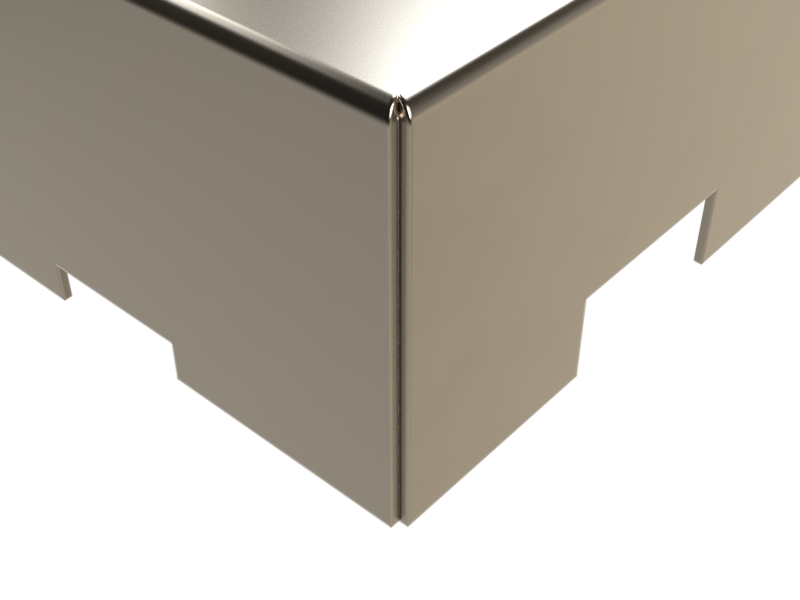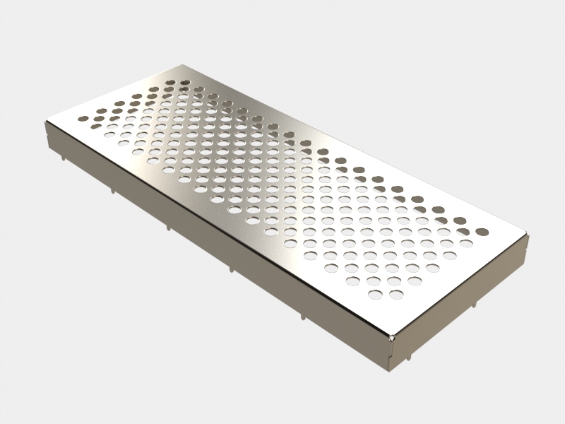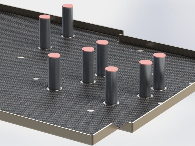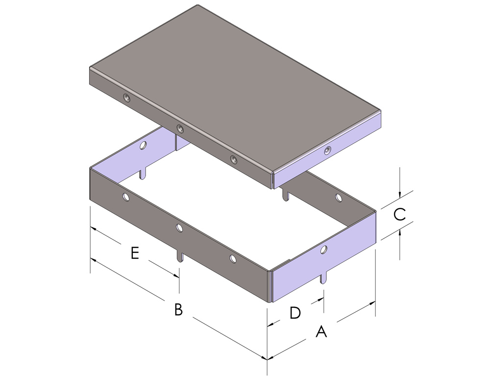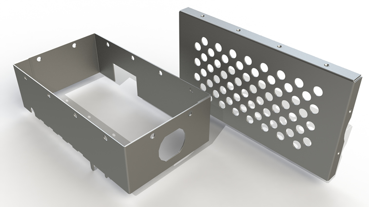
3G offer a variety of through-hole and surface mount attachment methods to securely bond the board level shield to the circuit board. Locating pins are placed on the bottom of the shield frame and mate to holes on the PCB. Locating pins are required for wave solder application but are also recommended for surface mount applications.
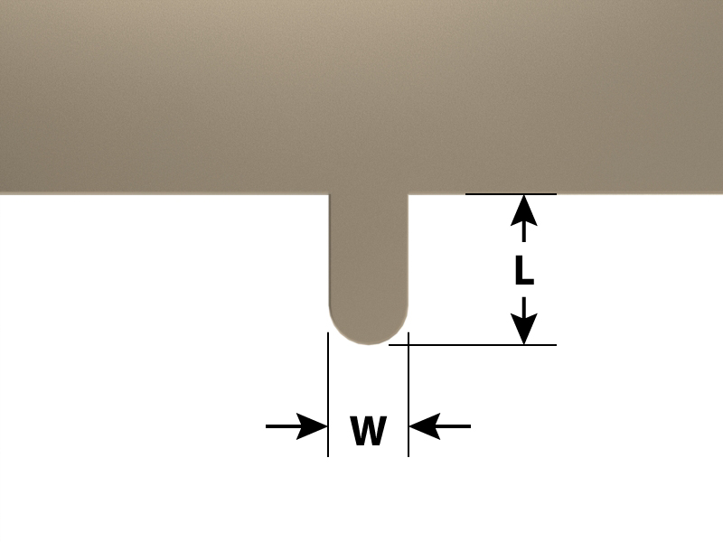
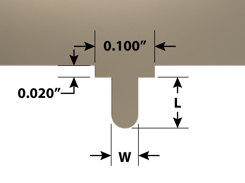
Alignment Pins

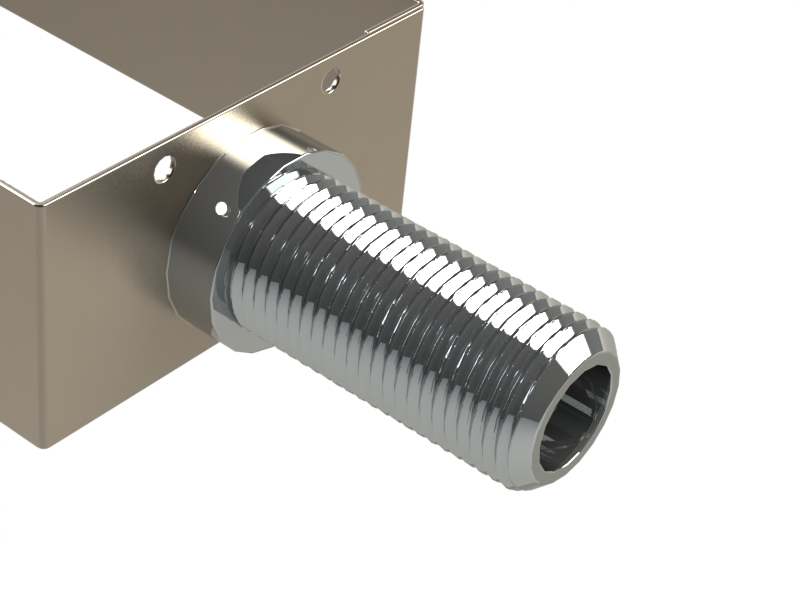
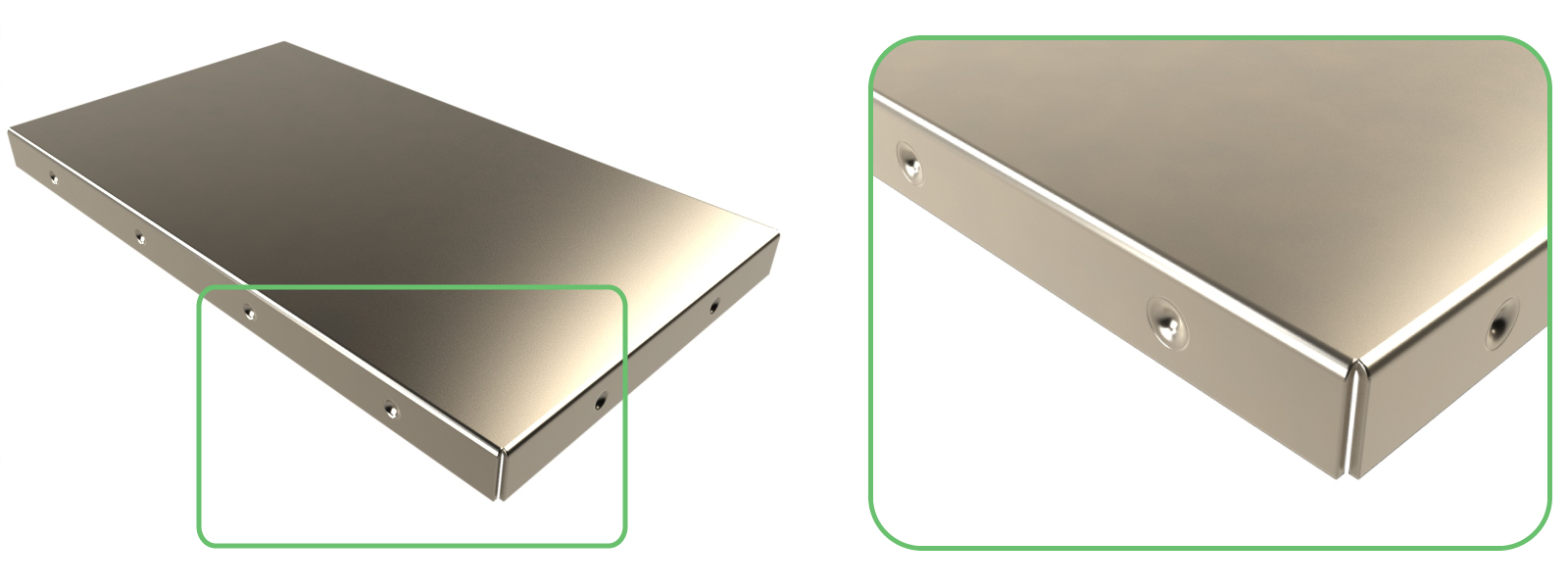
Through-Hole Pin
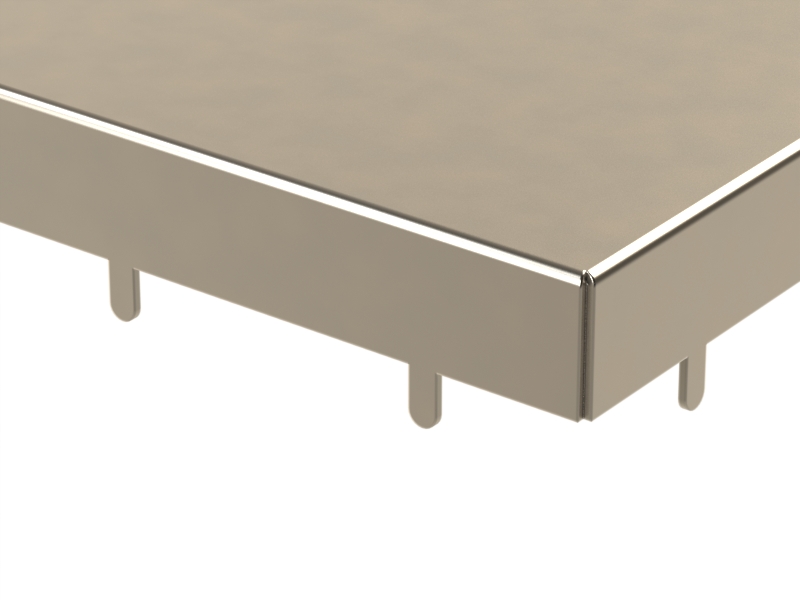
Pin w/Standoff
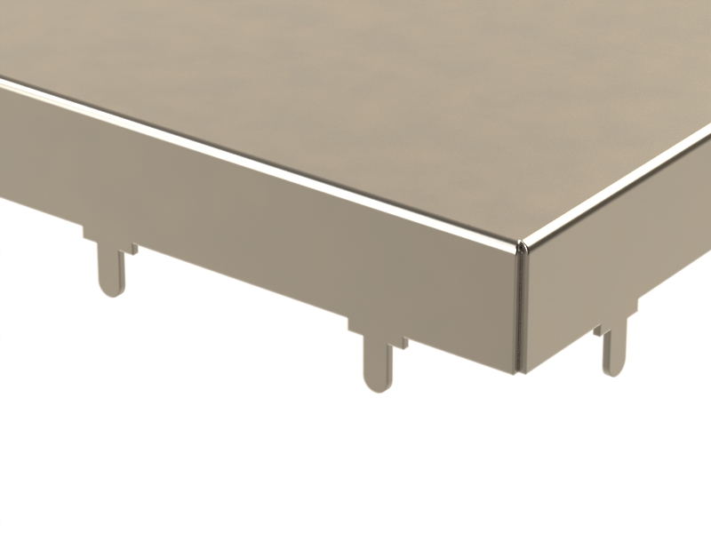
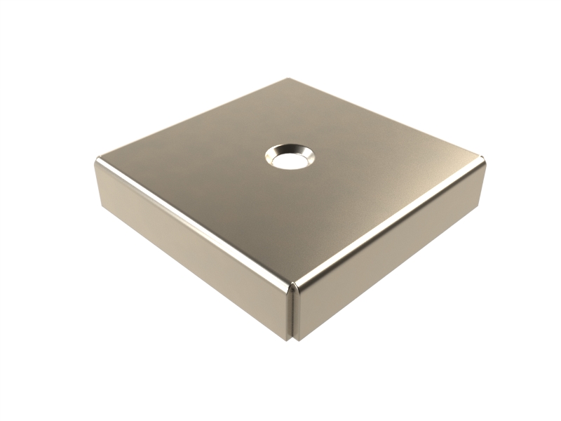
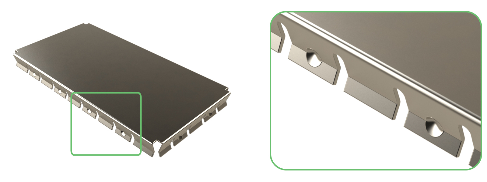
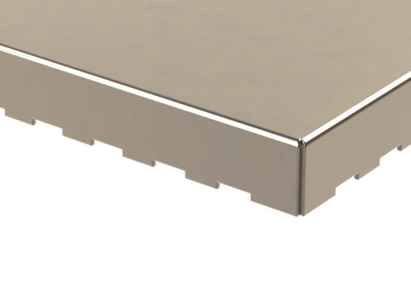
Castellation Edge
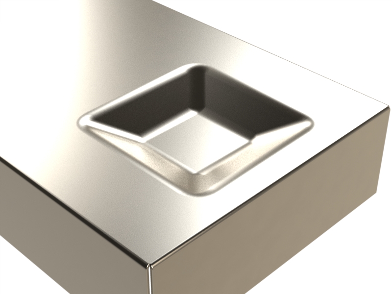
Knife Edge